Solidworks Sheet Metal Gap Distance

Powder Coating Oven 3dp Parts Powder Coating Oven Powder Coating Oven

This Time Something Twisted Made Two Videos Because One Would Be Too Long So Here Is The First Part For The Twisted Body I Solidworks Shape Design Blend
2017 Solidworks Edge Flange Propertymanager

Pin Em Cad Videos
2012 Solidworks Help Closed Corner

Solidworks Complex Sheet Metal Ege Flanges Youtube

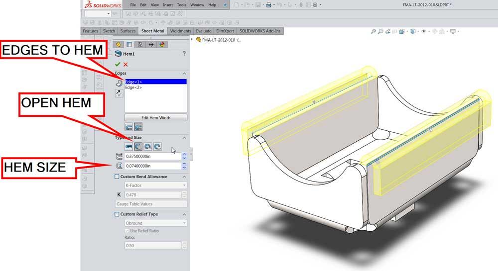
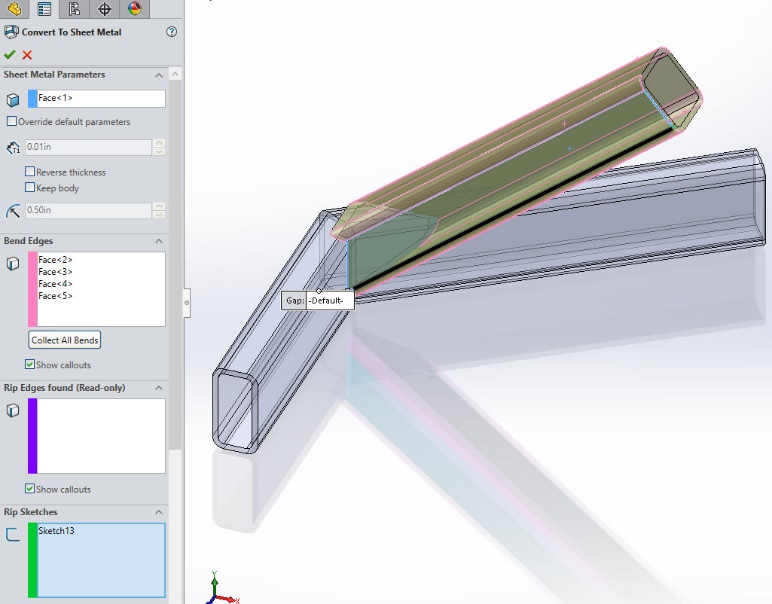
Adjust the gap distance.
Solidworks sheet metal gap distance.
2018 Solidworks Help Closed Corner Propertymanager

Solidworks 2016 Sheetmetal Edge Flange Extension Youtube
What Sheet Metal Shops Wish You Knew Hems Jogs And Forming Tools

Pin By Randy Kennedy On Metal Milling Lathe Machining Metal Projects Metal Lathe Tools Machining Projects

Pulley Belt Rpm Calculator Toan Học đồ điện Tử động Cơ

Solidworks Flat Pattern Archives
2018 Solidworks Help Edge Flange Propertymanager

Pin On Engineering

Miter Flange In Solidworks Youtube

Pulley Calculator Pulley Woodworking Woodworking Tools
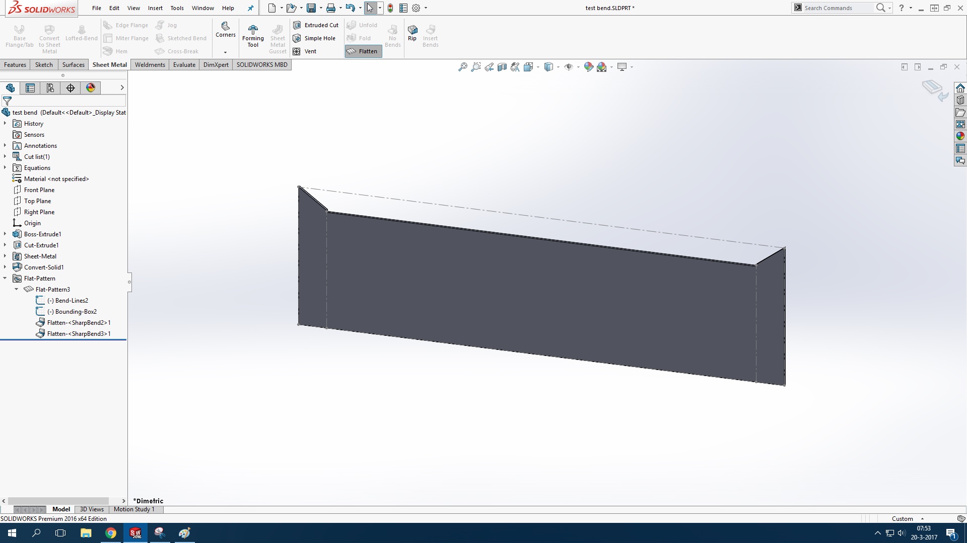
Flat Pattern Problem In Solidworks 2016 Grabcad Questions

Solidworks Creating A Coped Cut Perpendicular To A Pipe Youtube

Pin By Business Credit Builders Llc On Fabrication Concept Car Design Sheet Metal Work Custom Cars

Miter Flange Command Grabcad Questions
Solidworks Creating Templates For Weldment Fabrication

Cnc Furniture Furniture Cnc Home Decor

Double Action Deep Drawing Mechanical Power Press Maneklal Deep Drawing Mechanical Power Mechanic
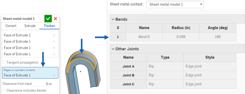
Sheet Metal Model
Https Encrypted Tbn0 Gstatic Com Images Q Tbn 3aand9gcrmqw31 Vjdd8nznm7 M5fmr7lgzacenrcperarvdocqr4rhetr Usqp Cau

Solidworks Quick Tip How To Mirror Parts Youtube

How To Use The Solidworks Clearance Verification To Check Assemblies

Solidworks Technical Tips Solidworks Videos Solidworks Promotion Solidworks Reseller January 2016
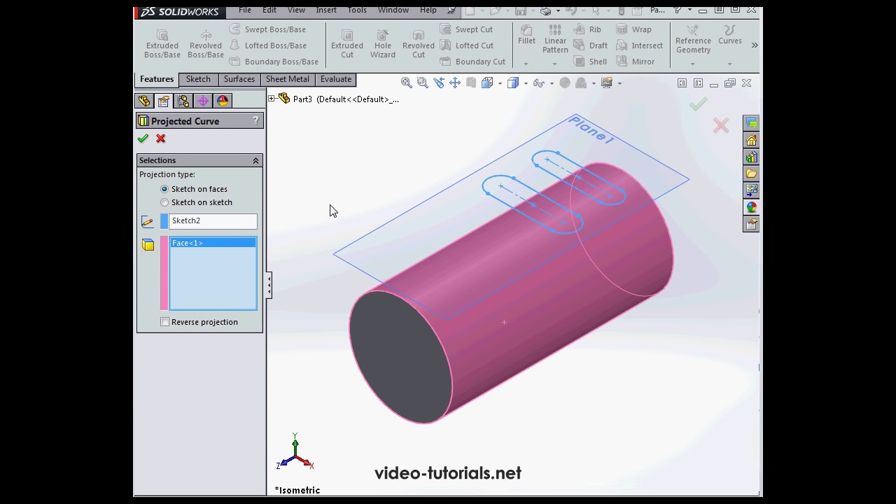
Slots On A Cylindrical Surface Solidworks Tutorials Q A Youtube
Source : pinterest.com
