Solidworks Strain Relief Sheet Metal

Auto Vs Corner Relief In Solidworks Sheet Metal

Managing Your Favorite Materials Using Materials Library In Solidworks

Sheet Metal Tutorial 2 How To Work With Sheet Metal In Autodesk Fusion 360 Sheet Metal Autodesk Tutorial

Solidworks Sheet Metal Tutorial Forming Tool Youtube Solidworks Tutorial Solidworks Sheet Metal

Solidworks Sheet Metal Lofted Bend Youtube Sheet Metal Drawing Solidworks Sheet Metal

Solidworks Sheet Metal Exercise Youtube Sheet Metal Drawing Sheet Metal Solidworks

Under scope select the sheet metal body to which to apply the corner relief.
Solidworks strain relief sheet metal.

Pin On Solidworks

Pin On Cam

Solidworks Sheet Metal 2d To 3d Sheet Metal Drawing Solidworks Tutorial Sheet Metal

Solidworks Sheet Metal Tutorial Forming Tool Youtube Solidworks Solidworks Tutorial Sheet Metal Drawing
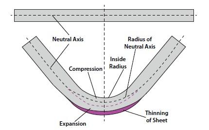
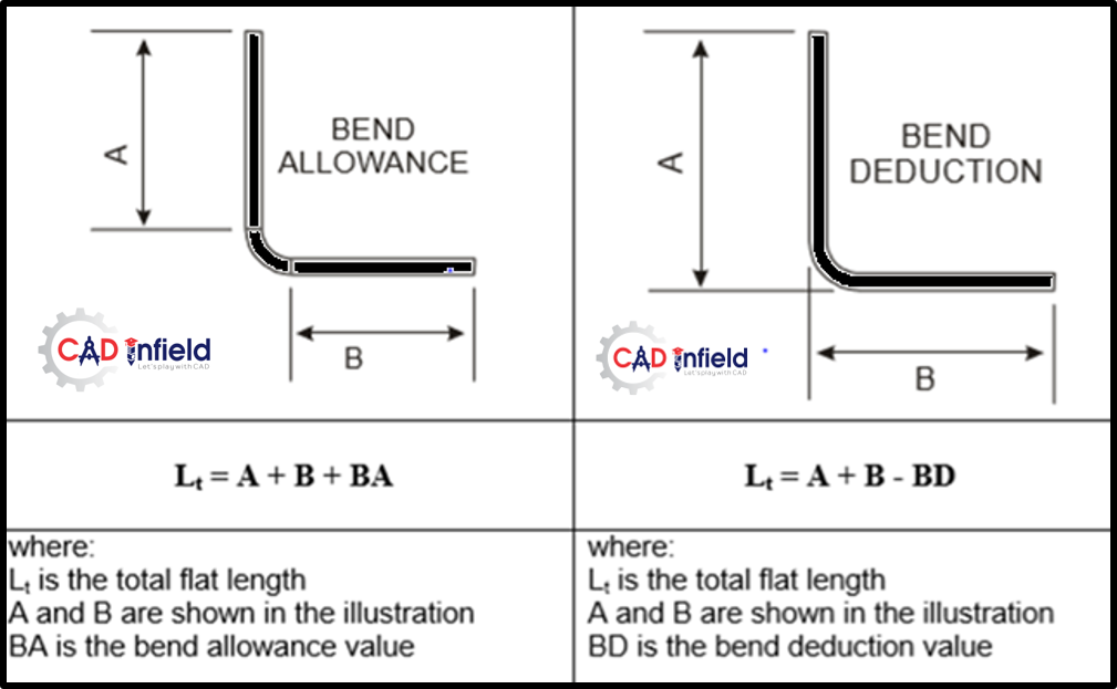
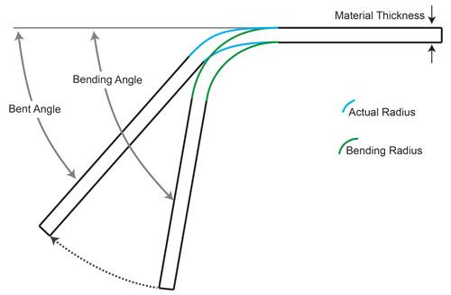
Analyzing The K Factor In Sheet Metal Bending

Video Tech Tip Working With The Corner Relief Option Within Solidworks Sheet Metal Youtube
Bend Order In Solidworks Sheet Metal Parts Solidworks Sheet Metal Solid Works
Sheet Metal Fabrication Fundamental Cad Infield Fabrication Design

Fab Drawing Simple Sheetmetal Part Drawings Graphic Solidworks

How To Work With Auto Relief Trim Solidworks Tutorials Sheet Metal Youtube

Oblique Cylinder Sheet Metal Pattern Development Youtube

New Tendency Click Shelf Steel Furniture Design Metal Sheet Design Sheet Metal
Bending Basics The Hows And Whys Of Springback And Springforward

How To Design A Car Wheel Rim On Autodesk Fusion 360 Fusion 360 Tutorial For Beginners Car Wheels Rims Wheel Rims Car Wheel

Pin On Moje Wedkowanie

Construction Set For Sheet Metal Scale Model Making Sheet Metal Drawing Sheet Metal Metal Tree Wall Art

Solidworks Tutorial Sketch Sheet Metal Screw In Solidworks Youtube Solidworks Tutorial Solidworks Sheet Metal
1
Design For Manufacture And Assembly

Press Brake Bending Basics A Guide To Sheet Metal Bending Machinemfg

Base Flange Tab Command Sheet Metal Tutorial Youtube
Https Dl Zwsoft Com Zw3d Pc Zw3d Marketing White Paper Zw3d White Paper Sheet Metal Design Pdf

Bending Metalworking Wikipedia
Source : pinterest.com
